Here I am used lm567 to detect desired frequency. It supports frequency between 0.01Hz and 500KHz .
Maximum ratings
- Supply voltage of 9V
- Output Current of 100 mA

Design example
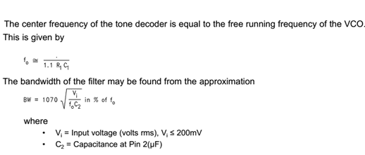
Here R1=10k, C1=0.01uF
Then fo=9090Hz
FREE RUNNING FREQUENCY =10.5KHz
But I got lock frequency = 11KHz

INPUT AT PIN 3 (BLUE) & OUTPUT AT PIN 8 (YELLOW)

OUTPUT SIGNAL WHEN THE FREQUENCY OF DESIGN RANGE NOT PRESENT (PIN 8 -YELLOW)

FREE RUNNING FREQUENCY OF VCO AT PIN5

OUTPUT AT PIN 6 (CAPACITOR CHARGING AND DISCHARGING -BLUE COLOUR)

OUTPUT AT PIN 1( BLUE COLOR)

OUTPUT AT PIN 2( BLUE COLOR)

OUTPUT AT PIN 3( BLUE COLOR)
EXAMPLE – IR TRANSMITTER(555) AND RECEIVER (LM567 )

Applications
- v IR sensors
- v Ultra sonic sensors
- v Frequency detector