
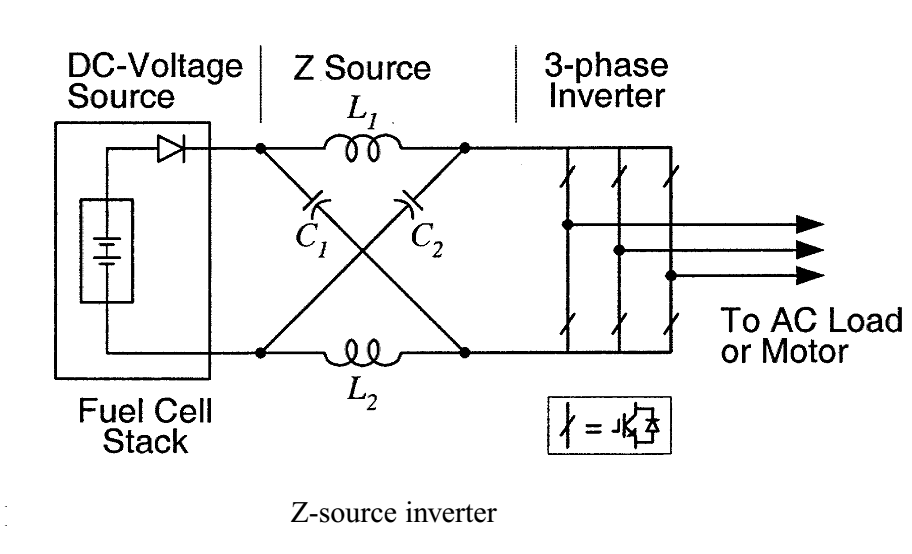
- POWER =16W
- VIN=12V
- IIN=1.33A
- VOUT=16V ,
- IOUT =1A
- Gain of converter = T /( TOFF -TON)
ON TIME CYCLE CALCULATION
Gain of converter = VOUT /VIN
Gain of converter = 16V /12V
Gain of converter =1.33
VOUT = VIN T /( TOFF -TON)
16 = 12 T /( TOFF -TON)
1.33 = T /( TOFF -TON)
TOFF = T-TON
take switching frequency is 60kHz
the time=16µs
1.33 = T /( T-TON -TON)
1.33 = T /( T -2TON)
1.33 = 16µs /( 16µs -2TON)
solving above we get
TON = 2µs
INDUCTOR VALUE CALCULATION
WHEN THE SHOOT THROUGH STATE , VIN= VL =12
FOR AN INDUCTOR VOLTAGE CURRENT BASIC RELATION IS
VL = L * dI / dt
THEN, L = VL * dt / dI
L = VIN * dt / dI
HERE dt =2µs —- DUTY CYCLE / FREQUENCY
Assume that operating frequency of the switch (mosfet here) =60 kHz
AND dI IS THE RIPPLE CURRENT OF INDUCTOR
IL = IIN =1.33A
Assume that inductor ripple current = 10% of inductor current
dI =10% * IL
dI = .133A
L = VIN * dt / dI
L = 12V * 2µs / .133A
L = 180µH
OUTPUT CAPACITOR C1 AND C2 VALUE
FOR A CAPACITOR VOLTAGE CURRENT BASIC RELATION IS
I = C * dV / dt
C = I * dt / dV
dV is output ripple voltage. Assume that output ripple voltage is about 0.01% of output voltage
dV = 0.01% * 18V
dV = 0.0016 V
C = I * dt / dV
C = 1.33 * 2µs / 0.0016
C = 1662µF
SIMULATION
3-PHASE SIMULATION


3-PHASE GATE SIGNAL TABLE

SINGLE PHASE
HARDWARE – SINGLE PHASE

CIRCUIT – SINGLE PHASE

GATE SIGNALS WITH SHOOT THROUGH – SINGLE PHASE


Program – single phase (compiler – mikro c for dspic)
//crystal of 16 MHz
#define s1   LATE.F0        //S1
#define s2   LATE.F1        //S2
void main()
{
    TRISE.F0=0;TRISE.F1=0;
    s1=0;s2=0;
    while (1)
    {
        s1 =1;   Delay_us(15);   s2 =1;Delay_us(2);s1 =0;
        s2 =1;   Delay_us(15);   s1 =1;Delay_us(2);s2 =0;
    }
}
Program – 3 phase – not tested it with hardware (compiler – mikro c for dspic)
//crystal of 16 MHz
#define s1   LATE.F0        //S1
#define s2   LATE.F1        //S2
#define s3   LATE.F2        //S3
#define s4   LATE.F3        //S4
#define s5   LATE.F4        //S5
#define s6   LATE.F5        //S6
void main()
{
    TRISE.F0=0;TRISE.F1=0;TRISE.F2=0;TRISE.F3=0;
    TRISE.F4=0;TRISE.F5=0;
    s1=0;s2=0;s3=0;s4=0;s5=0;s6=0;
    while (1)
    {
        s1 =1;s3 =1;s5 =1;   Delay_us(16);   s6 =1;Delay_us(1);s3 =0;
        s1 =1;s6 =1;s5 =1;   Delay_us(16);   s2 =1;Delay_us(1);s5 =0;
        s1 =1;s6 =1;s2 =1;   Delay_us(16);   s4 =1;Delay_us(1);s1 =0;
        s4 =1;s6 =1;s2 =1;   Delay_us(16);   s3 =1;Delay_us(1);s6 =0;
        s4 =1;s3 =1;s2 =1;   Delay_us(16);   s5 =1;Delay_us(1);s2 =0;
        s4 =1;s3 =1;s5 =1;   Delay_us(16);    s1 =1;Delay_us(1);s4 =0;
    }
}